mercredi 21 décembre 2011
arduino unipolar motor stepper
mardi 20 décembre 2011
arduino to stepper
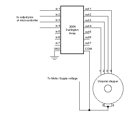
Montage Arduino à base de driver à base de ULN2003A.
Une page de référence.
le montage unipolaire

Les composants U2004 darlington
Le montage bipolaire

Schéma

Les composant 75441one
Un autre piste à l'aide d'un L293D.
lundi 19 décembre 2011
Ardubloc ide for arduibo
1.Download ardublock-all.jar ArduBlock
2. In Arduino IDE, open menu “Arduino” -> “Preferences”
3. Find “Sketchbook location:”
- In Mac, it’s by default “Documents/Arduino” under user’s home directory
- In Linux, it’s by default “sketchbook” under user’s home director
- In Mac, /Users/abu/Documents/Arduino/tools/ArduBlockTool/tool/ardublock-all.jar
- In Linux, /home/abu/sketchbook/tools/ArduBlockTool/tool/ardublock-all.jar
- In Windows, C:\Users\abu\Documents\Arduino
5. Start the Arduino IDE and find ArduBlock under the Tool menu
Example of a ArduBlock Program
The drawers of ArduBlock are divided into 6 different categories.
Control
Control blocks are for program flow control
Numbers, Constants and Variables
These blocks provide access to computational data
Operators
These blocks provides operators for logical and mathematical computation
Utilities
These blocks provide access to utilities functions provided by Arduino platform
Bricks
These blocks provide more intuitive access to electronic bricks system.
Pin
This drawer probably needs a better name. The blocks here provide I/O access to Arduino Pins
Handling Digital Input and Output
The block below basically represent the “Hello World” of Arduino Programming mapping to the code fragments
if (digitalRead(1) == HIGH) { digitalWrite(2, HIGH); } Multiple events on the same pin should be support by defining multiple events on the same pin. It seems that a good visual grouping of the same pin would be a good thing and improve readability of the program.
The OpenBlocks come with a pretty cool annotation system to add comments to block. This could be leveraged to enhance the readability of the program.
Handling Analog Input and Output
The analog I/O handling should work the same way as the digital one.
Doing conditional statements with Pin. The Pin 3 is identified with color in the ‘if’ statement. Maybe a label on it will work better.
Functional Programming or Object Oriented?
Since Clojure is used as programming language to drive the ArduBlock, it seems that it pushes my design of the block language to have more functional programming favor. It may be a good thing to make program more straight forward to understand and to program. But really need to guard against the tunnel vision.
Rule Engine?
Since I am using a rule engine in a project right now, I may also be influenced by that. I see all these blocks laying out conditions to trigger actions. It may be worth a while to see if a small Reta Algorithm can be easily implemented in Arduino to handle the rules layout by the blocks. This seems to be a nature way to design a run time for this language.
Design I
The first design is of course to follow the Arduino Language Reference closely. However, the resulting block language seems to be a bit too “verbose?” Or should I say “busy” since it’s really a graphical representation of the textual program. Here is a sample of what it looks like for the equivalence of codes here.
void setup() { pinMode(1, INPUT); pinMode(2, OUTPUT); } void loop() { if (digitalRead(1) == HIGH) { digitalWrite(2, LOW); } } Design II
Since the block language is targeted at the beginner of Arduino and programming, most of time, we talk about “When the button on pin 1 is pushed, I want the LED on pin 2 to light up.” There is a much natural way to map this statement into an intuitive block language by building the blocks around the pin. Here is how it may look like:
This language is more concise and easier to understand. The language itself should provide enough meta info to infer the setup codes. However, in order to do this, the language may need a little runtime (OS?) to be compiled along with the Sketch but it seems to be worth the effort.
The OpenBlocks codes I am playing around with the idea is available at my openblocks on github. Appreciate any feedback on this.
source:
mardi 13 décembre 2011
processing -> arduino -> servo
Code processing
import controlP5.*;
import processing.serial.*;
Serial myPort; // The serial port
ControlP5 controlP5;
public int myColorRect = 200;
public int myColorBackground = 100;
//variable global
int slide1;
void setup() {
size(400,400);
frameRate(25);
controlP5 = new ControlP5(this);
controlP5.addSlider("sliderA",63,118,100,100,260,100,14).setId(4);
controlP5.addTextfield("textA",100,290,100,20).setId(5);
println(Serial.list());
String portName = Serial.list()[0];
myPort = new Serial(this, portName, 9600);
}
void draw() {
background(myColorBackground);
fill(myColorRect);
rect(0,0,width,100);
myPort.write(slide1);
}
// a slider event will change the value of textfield textA
public void sliderA(int theValue) {
((Textfield)controlP5.controller("textA")).setValue(""+theValue);
}
// for every change in textfield textA, this function will be called
public void textA(String theValue) {
println("### got an event from textA : "+theValue);
slide1=int(theValue);
println("slide 1 : "+slide1);
}
public void controlEvent(ControlEvent theEvent) {
println("got a control event from controller with id "+theEvent.controller().id());
}
Code arduino
#include
Servo myservo;
int incomingByte = 0; // for incoming serial data
void setup() {
Serial.begin(9600); // opens serial port, sets data rate to 9600 bps
myservo.attach(9); // attaches the servo on pin 9 to the servo object
}
void loop() {
int pos;
// send data only when you receive data:
if (Serial.available() > 0) {
// read the incoming byte:
incomingByte = Serial.read();
// say what you got:
Serial.print("I received: ");
Serial.println((int)incomingByte, DEC);
pos=int(incomingByte);
myservo.write(pos); // tell servo to go to position in variable 'pos'
delay(15);
}
}
Et voila ca marche
Il a juste fallut régler la plage de valeur du servo pour ne pas le mettre en buté. La consomation du servo est également à surveiller. Parfois il demande pas mal mais c'est surtout quand il arrive en butée. Généralement et en fonctionnement normal c'est de l'ordre de 0,10 à 0,30A max
mercredi 7 décembre 2011
I2c et arduino
site;
http://wiki.t-o-f.info/index.php?n=Arduino.I2C
http://www.arduino.cc/cgi-bin/yabb2/YaBB.pl?num=1235582397
http://arduino.cc/en/Tutorial/MasterWriter
http://www.gammon.com.au/forum/?id=10896
Les questions:
1-/Comment brancher les 2 aduinos en i2c?
2-/Comment transformer un des arduinos en maitre et esclave?
Comment lire les données sur l'un des arduino et vérifier qu'il récupère bien les bonnes données?
Réponses:
1-/Sur la plupart des cartes Arduino:
SDA : broche analogique 4
SCL : broche analogique 5
Un bus I2C (pour Inter Integrated Circuit) est un bus série et synchrone composé de trois fils :
un signal de donnée (SDA) ;
un signal d'horloge (SCL) ;
un signal de référence (masse).
Le périphérique qui gère la communication est le maître, c'est lui qui génère l'horloge (SCL) et qui envoie les données (SDA) mis à part l'acknowledge (acquittement en français).
source : http://fr.wikipedia.org/wiki/I2C
2-/Le brochage est toujours le même pour l'esclave et le maitre. Pas encore bien compris pourquoi.
Exemple maitre/esclave
Code:
#include
void setup()
{
// initialise la liaison I2C en tant que maitre (pas de paramètre à begin)
Wire.begin();
}
void loop()
{
// commence à parler à la carte slave qui a déclaré l'adresse 0x01
Wire.beginTransmission(0x01);
Wire.send("Salut"); // envoie une chaine de caractères (pourrait être un tableau de byte ou...)
Wire.endTransmission(); // arrête
delay(500);
}
Sur l'esclave :
Code:
#include
void setup()
{
// initialise l'I2C en tant que slave (puisque il précise l'adresse 0x01
Wire.begin(0x01);
// déclare une fonction (ci-dessous) pour recevoir ce que le maitre envoit
Wire.onReceive(recevoir);
// pour pouvoir dire ce qui se passe
Serial.begin(9600);
}
void loop()
{
// rien de particulier, le code normal de la carte
delay(100);
}
// déclenché par un envoi du maitre
void recevoir(int qty)
{
Serial.print("> J'ai reçu ");
Serial.print(qty);
Serial.println(" octets.");
// on lit octet par octet
Serial.print("Le maitre dit : ");
while(Wire.available() > 0)
{
char c = Wire.receive();
Serial.print(c);
}
// dernier retour à la ligne
Serial.println();
}
Exemple de transmssion pour un capteur an i2C. Ca peut toujours servir
/*
SRF02 sensor reader
language: Wiring/Arduino Reads data from a Devantech SRF02 ultrasonic sensor.
Should also work for the SRF08 and SRF10 sensors as well.
Sensor connections:
SDA - Analog pin 4
SCL - Analog pin 5
created 5 Mar. 2007
by Tom Igoe
*/
// include Wire library to read and write I2C commands:
#include
// the commands needed for the SRF sensors:
#define sensorAddress 0x70
#define readInches 0x50
// use these as alternatives if you want centimeters or microseconds:
#define readCentimeters 0x51
#define readMicroseconds 0x52
// this is the memory register in the sensor that contains the result:
#define resultRegister 0x02
void setup()
{
// start the I2C bus
Wire.begin();
// open the serial port:
Serial.begin(9600);
}
void loop()
{
// send the command to read the result in inches:
sendCommand(sensorAddress, readInches);
// wait at least 70 milliseconds for a result:
delay(70);
// set the register that you want to reas the result from:
setRegister(sensorAddress, resultRegister);
// read the result:
int sensorReading = readData(sensorAddress, 2);
// print it:
Serial.print("distance: ");
Serial.print(sensorReading);
Serial.println(" inches");
// wait before next reading:
delay(70);
}
/*
SendCommand() sends commands in the format that the SRF sensors expect
*/
void sendCommand (int address, int command) {
// start I2C transmission:
Wire.beginTransmission(address);
// send command:
Wire.send(0x00);
Wire.send(command);
// end I2C transmission:
Wire.endTransmission();
}
/*
setRegister() tells the SRF sensor to change the address pointer position
*/
void setRegister(int address, int thisRegister) {
// start I2C transmission:
Wire.beginTransmission(address);
// send address to read from:
Wire.send(thisRegister);
// end I2C transmission:
Wire.endTransmission();
}
/*
readData() returns a result from the SRF sensor
*/
int readData(int address, int numBytes) {
int result = 0; // the result is two bytes long
// send I2C request for data:
Wire.requestFrom(address, numBytes);
// wait for two bytes to return:
while (Wire.available() < 2 ) {
// wait for result
}
// read the two bytes, and combine them into one int:
result = Wire.receive() * 256;
result = result + Wire.receive();
// return the result:
return result;
}
resultat